Parametric Generator
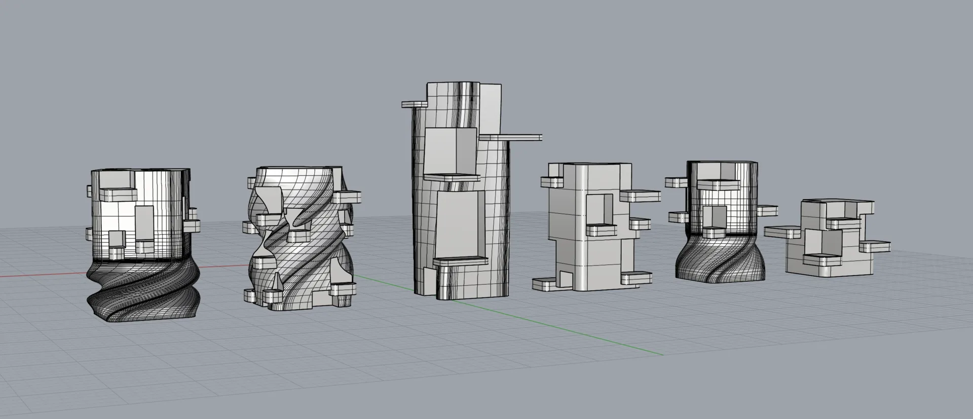
I wanted to create a primary shape with cavities - I ended up with abstract sci fi buildings.
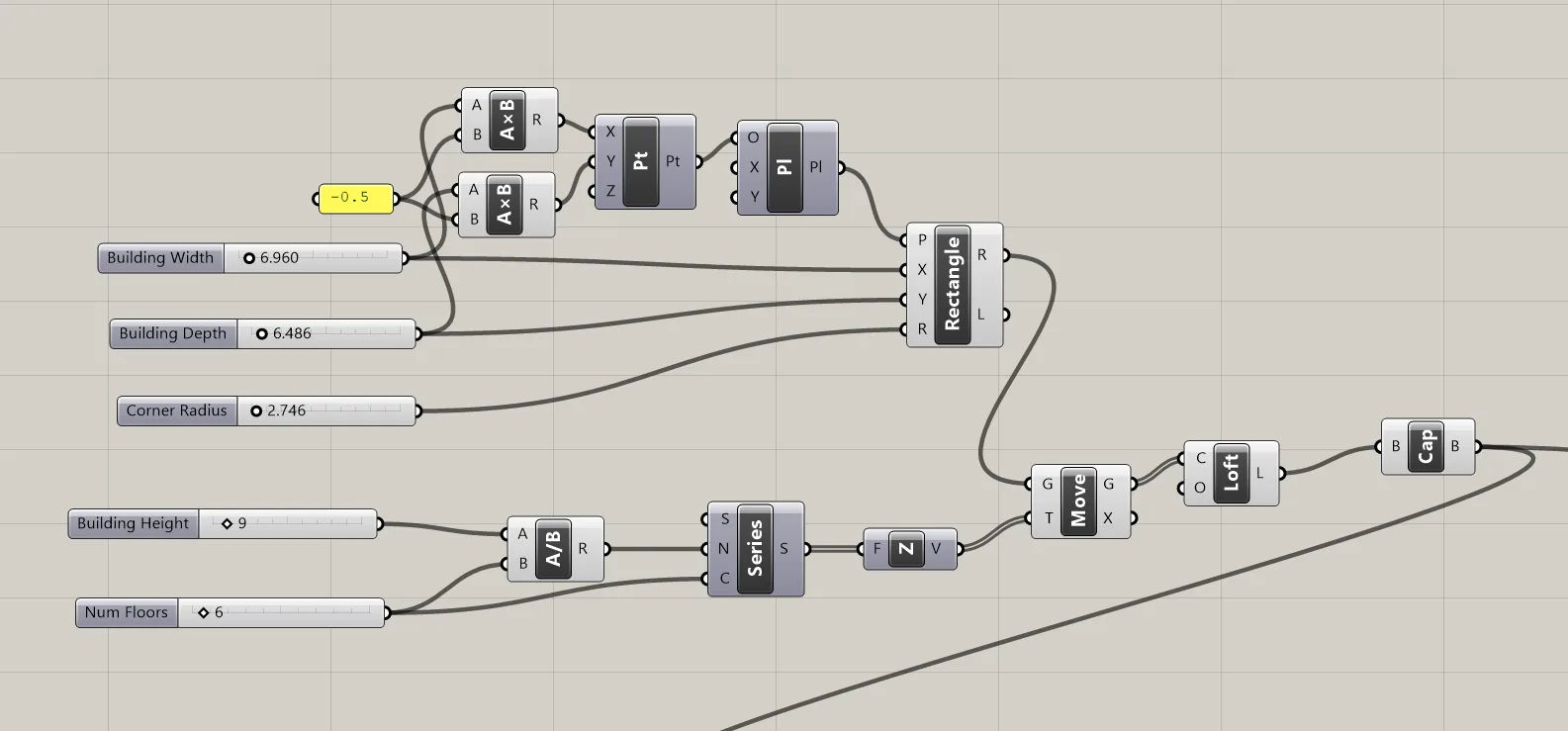
Primary Shape
First I created a primary shape out of lofted rectangles.
The parameters for this core shape were width, depth, corner radius, for the first rectangle.
This rectangle was then moved in series to create floors, parameterized with overall building height, and Num floors.
Initially I wanted to use floor positions to drive room layout but I ended up with a random approach so this parameter is not used.
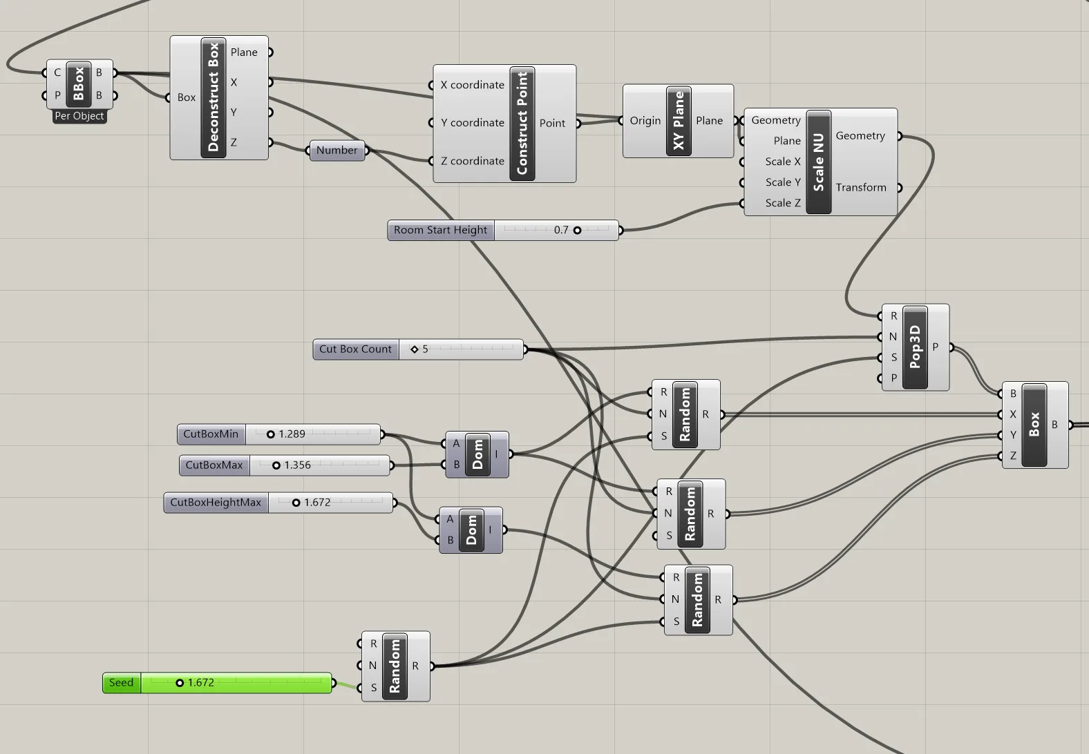
Rooms
The room positions were created with Pop3D node, using the bounding box of the primary shape as a region. The bounding box was scaled from above by Room Start Height in order to have rooms start higher in the building if needed.
Boxes were instantiated at each point, with random dimensions parameterized by Cut Box Min, (room min horizontal size), Cut Box Max, and Cut Box Max Height. Each random node, and the Pop3D, are given a seed parameter to try different layouts using the same parameters.
Eventually these boxes are cut from the main shape with a boolean difference node.
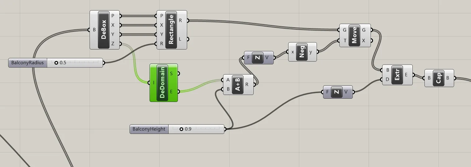
Balconies
To make the boxes more “room like” I added balconies. A rectangle is created at the bottom plane of the room’s bounding box, and extruded downard.
Balconies can be adjusted with Balcony Height and Balcony Radius.
Balonies are joined with the main shape with boolean union.
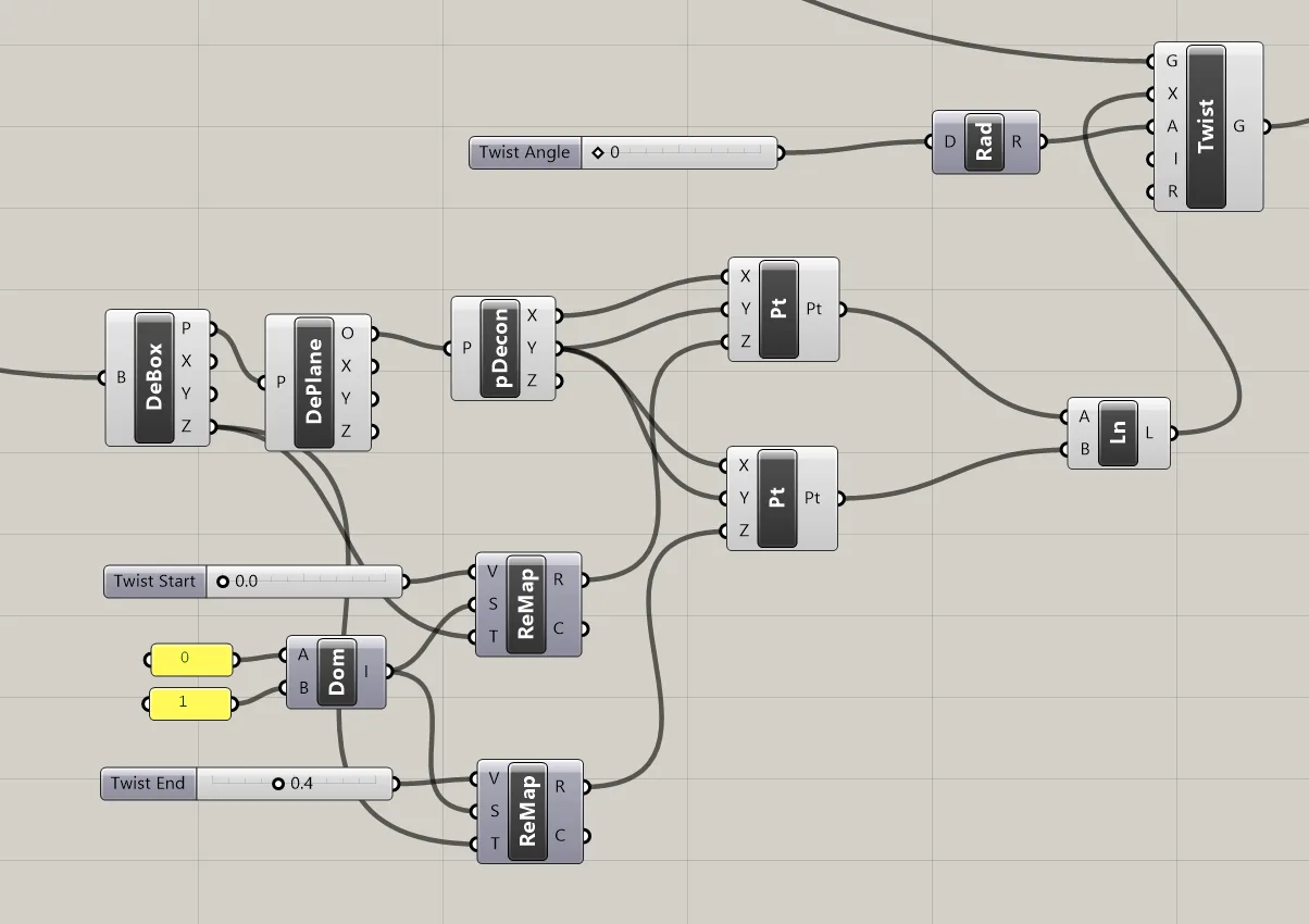
Twist
Prior the joining the pieces together, the main form is twisted by an arbitrary angle. In addition to twist angle, I added twist start and twist end parameters, by percentage of total building height, so I could only twist part of the building. This allows a twisted base, with rooms sitting on top, for example.
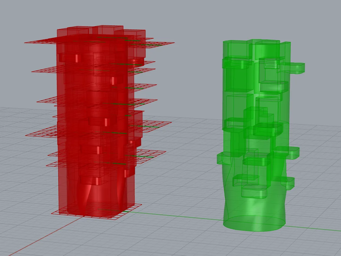
Final Form
To create the complete shape, the main form i twisted, the balconies are added to the main form, and the rooms subtracted from the main form, above each balcony.
Parameters Used:
Width, Depth, Corner radius, Building Height, Room Start Height, Cut Box Min, Cut Box Max, Cut Box Max Height, Balcony Height, Balcony Radius, Twist Angle, Twist Start, Twist End
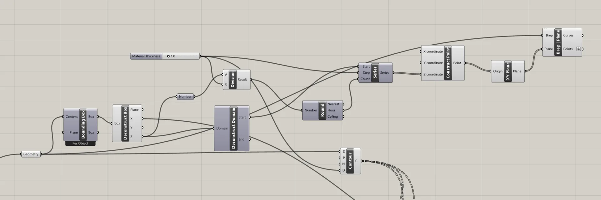
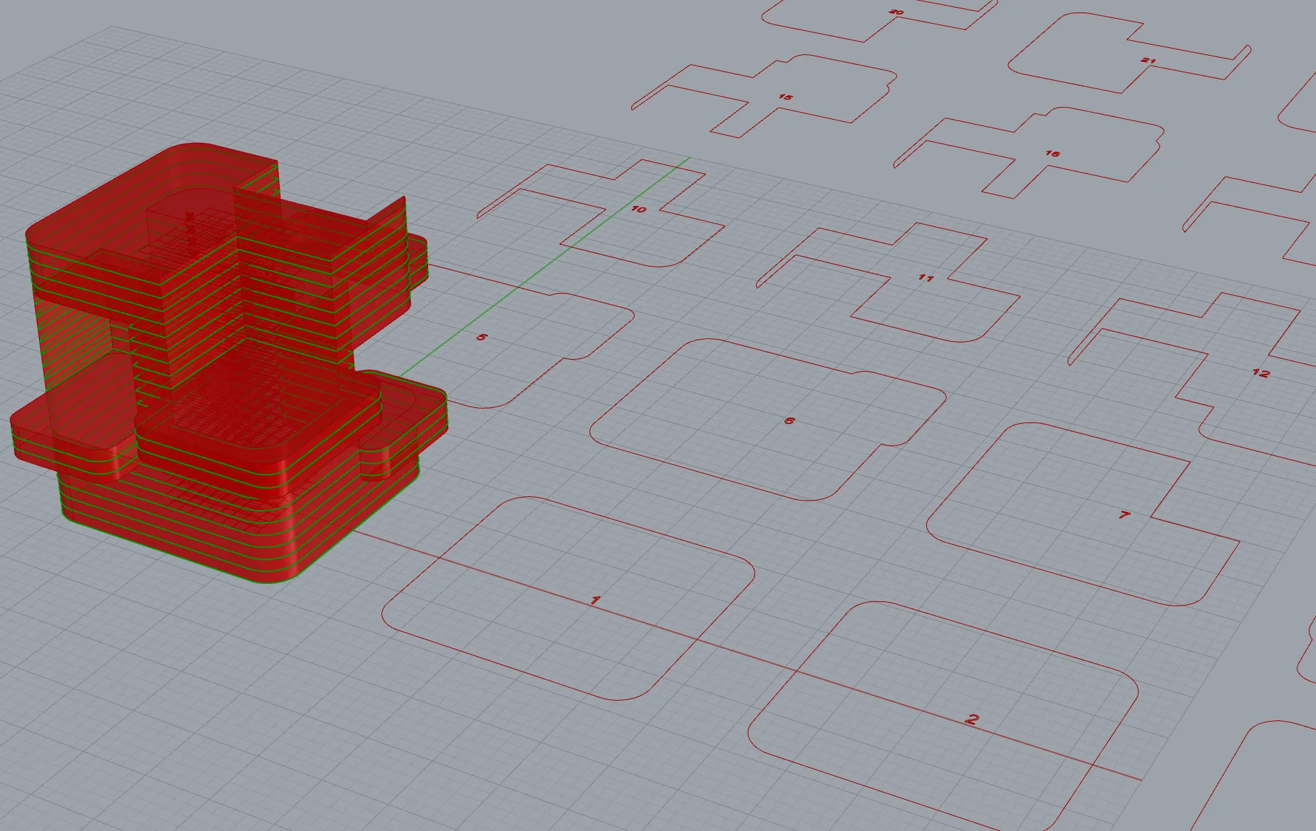
Slicer
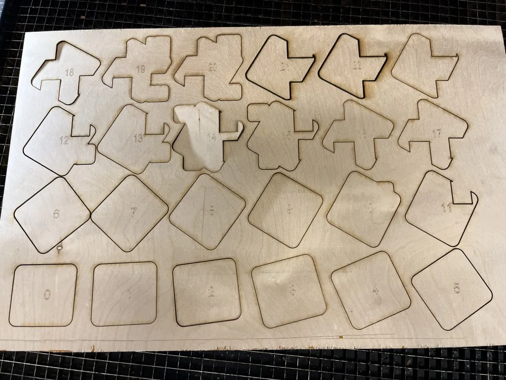
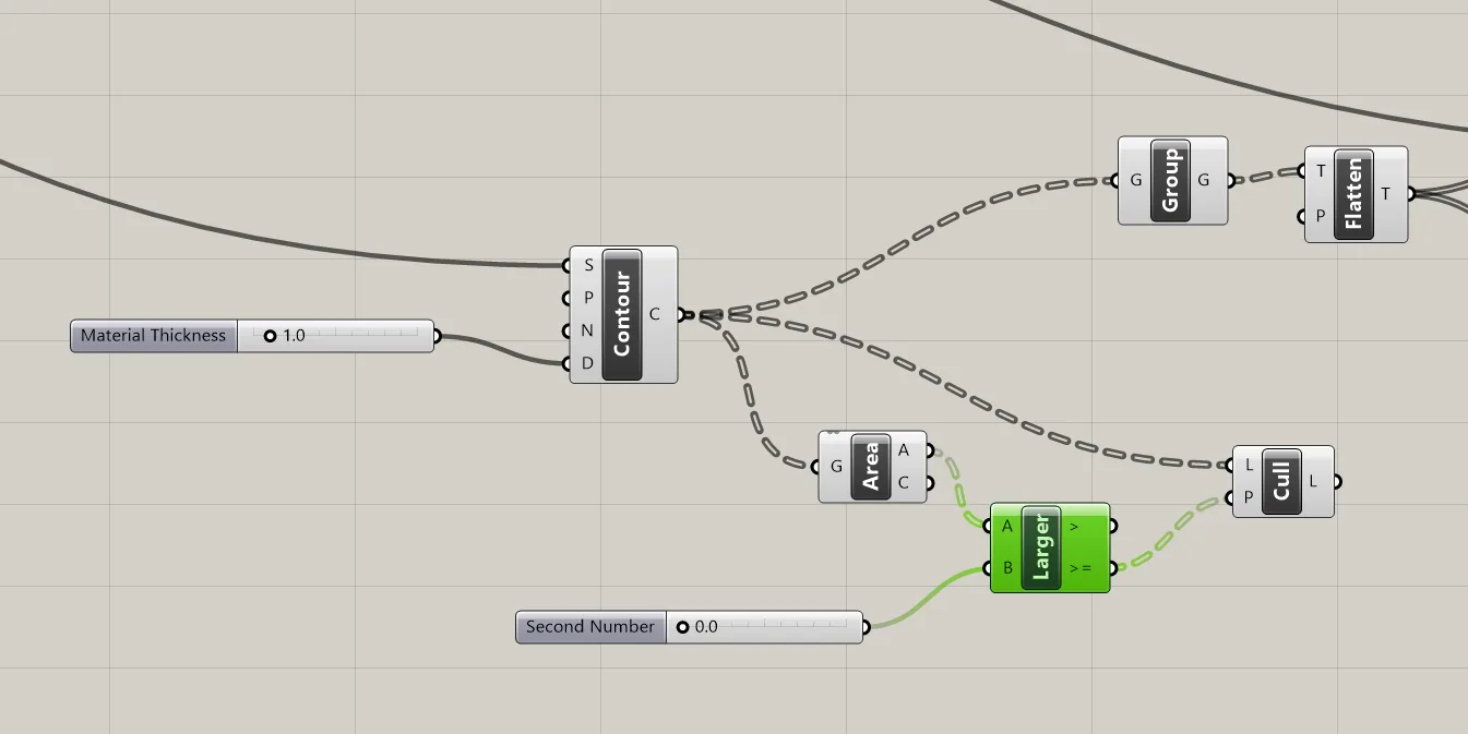
Initially I created contour slices using Brep Plane, but the Contour node did the same job with fewer nodes.
The contours are fed into a culling pattern node, with curves smaller than an certain area being culled. I ended up not needing this feature for my slices so I ignored it.
The contours were grouped into objects, and procted on the ground plane. I constructed a grid of points by cross referencing two series nodes - the width and height of the grid, determined by dividing the total number of slices. The projected curves were moved using the points in this grid.
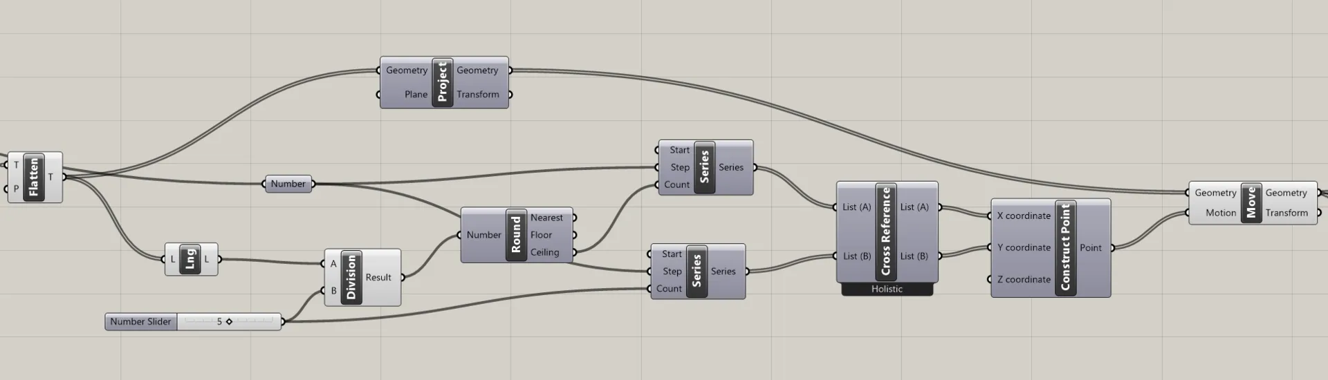
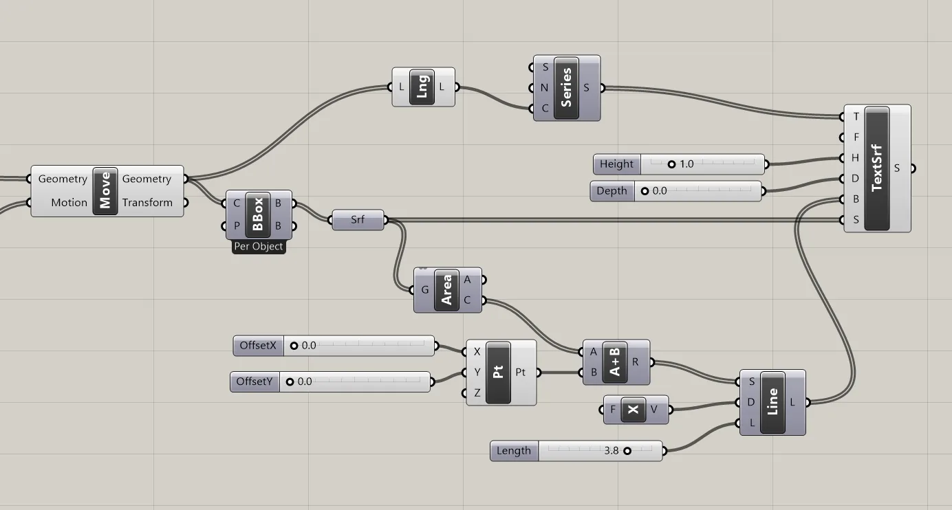
To assign text labels to each slice, I used the bounding box of each slice as a surface to project on to, and constructed the base line from the center of the surface area by lenth - then used Text to Surface node using those as surface and base line.
Sliced
Grasshopper Files
https://drive.google.com/drive/folders/1m-SR6j5n84r4U41L_Hr6FvTuCG0hBMGs?usp=sharing
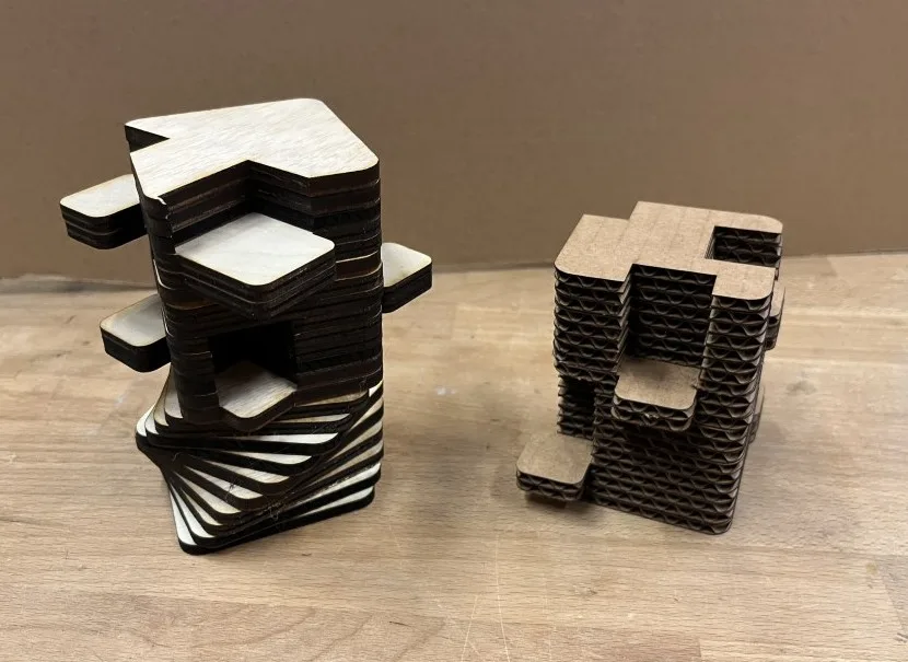
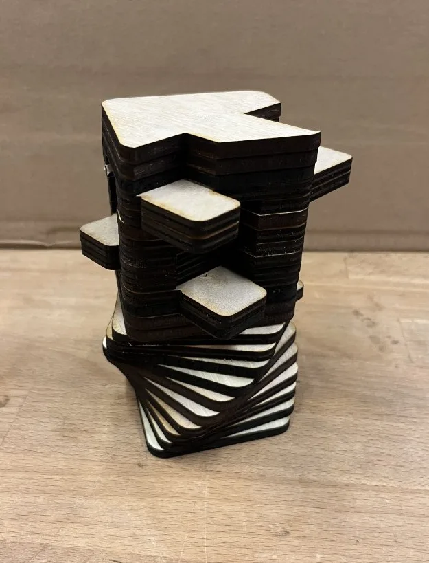
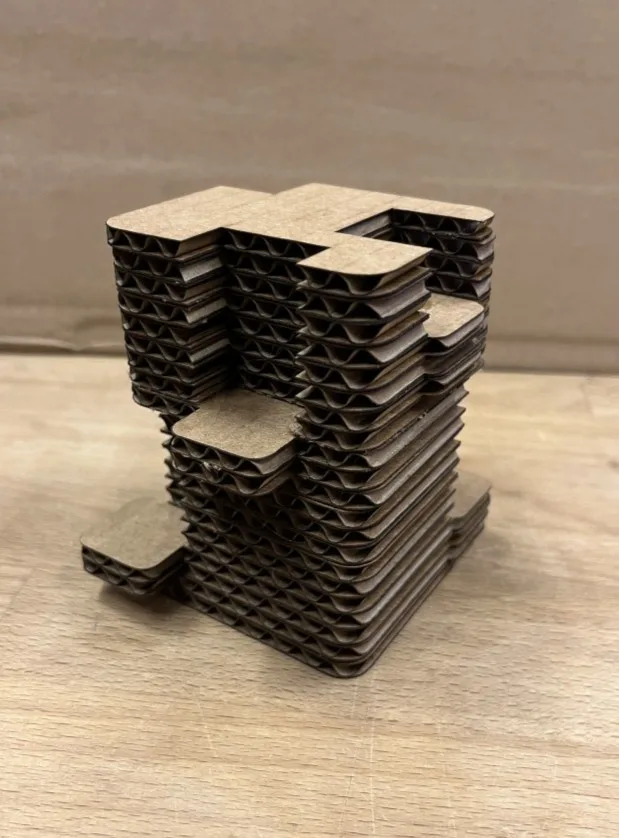
Fabrication
The slices were laser cut in wood and cardboard. I’m not sure if these shapes lend themselves particularly well to contour slicing, as the shapes look much better in 3D, but the fabrication process was successful.