Slicer
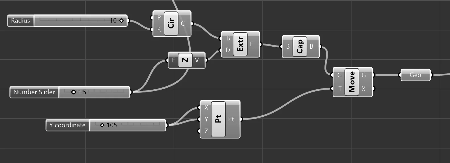
First I created the test cylinder and centered on the plate:
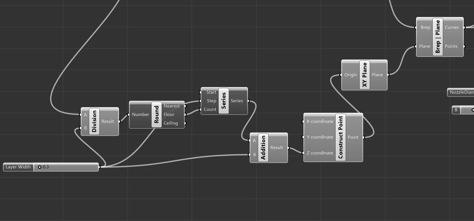
I used brep | plane node to create countour curves, using planes offset by the layer width. (Contour node made it harder to control start plane).
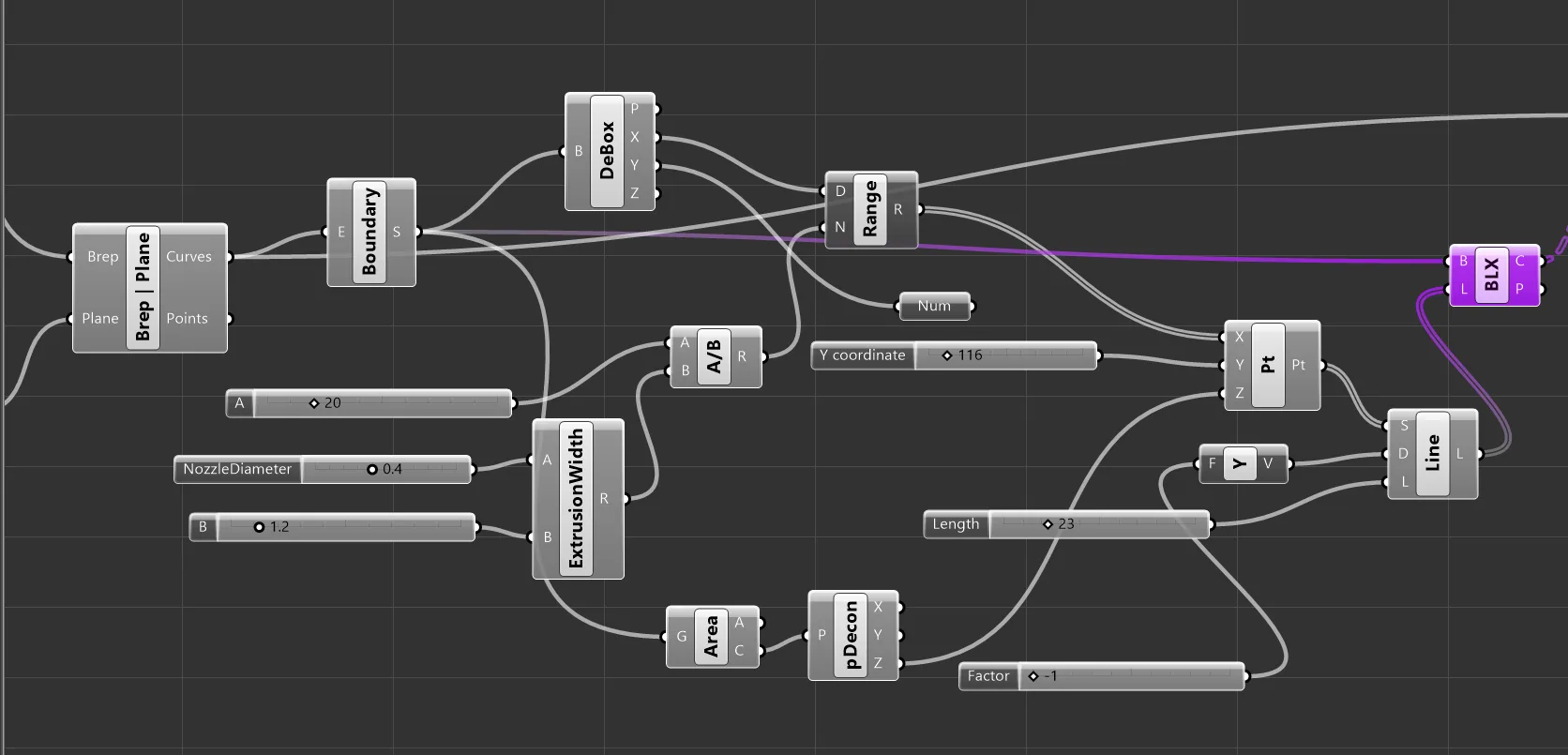
To begin the vertical infill lines, I got the boundary surfaces of the contours. To get the starting X position of the lines, I deconstructed the boundary with debox and used the x region as the domain of a range node, with the number of divisions within the range equal to the total diameter of the test cylinder divided by the extrusion width. This gave me X positions between 95 and 115. I created a point from these x positions and set Y to just above the circle boundary (115) and to the z position of the contour boundary.
I used these points as the start point of an SDL line, setting the direction to -1y and the length to a little more than the diameter of the cylinder.
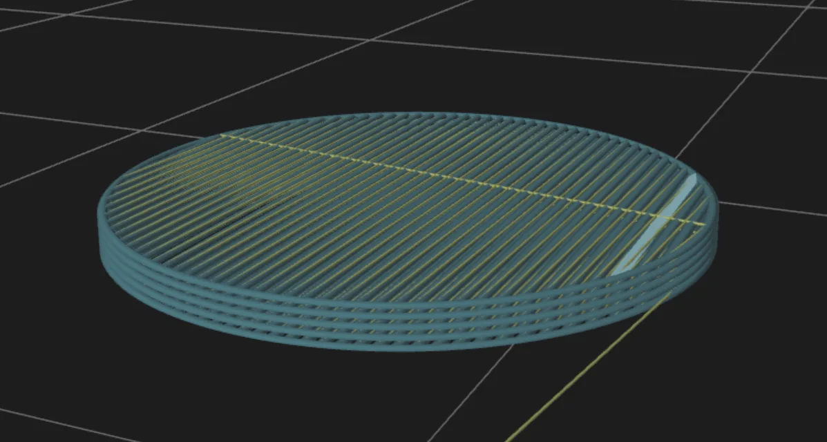
This created infil lines crossing through the cylinder. (A 3x height cylinder pictured here for multiple contours.)
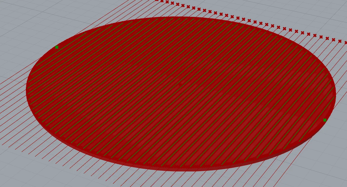
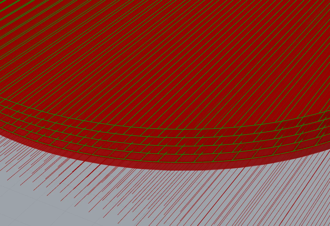
The excess line length was culled using BREP|Line intersection and the result is lines filling the contour. These are merged with the original contour lines to create the infill layer.
Before being merged, I grafted the Boundary Lines tree, and trimmed the infill lines tree, so when merged the result was 3 (or however many) flat arrays containing the boundary and its infill lines.
I used divide distance on the merged infill curves to create points 0.1mm apart. These points are used as the input of a polyline node, creating line segments 0.1mm long. The SimplifyCurves node consolidated long, straight segments (the cross section lines.)
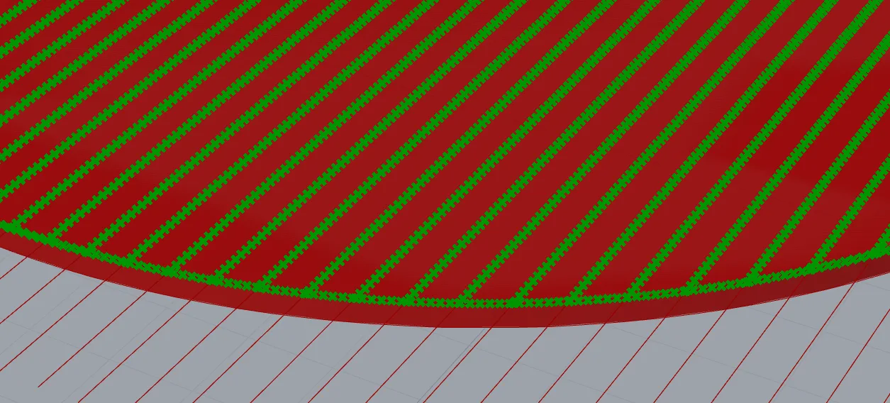
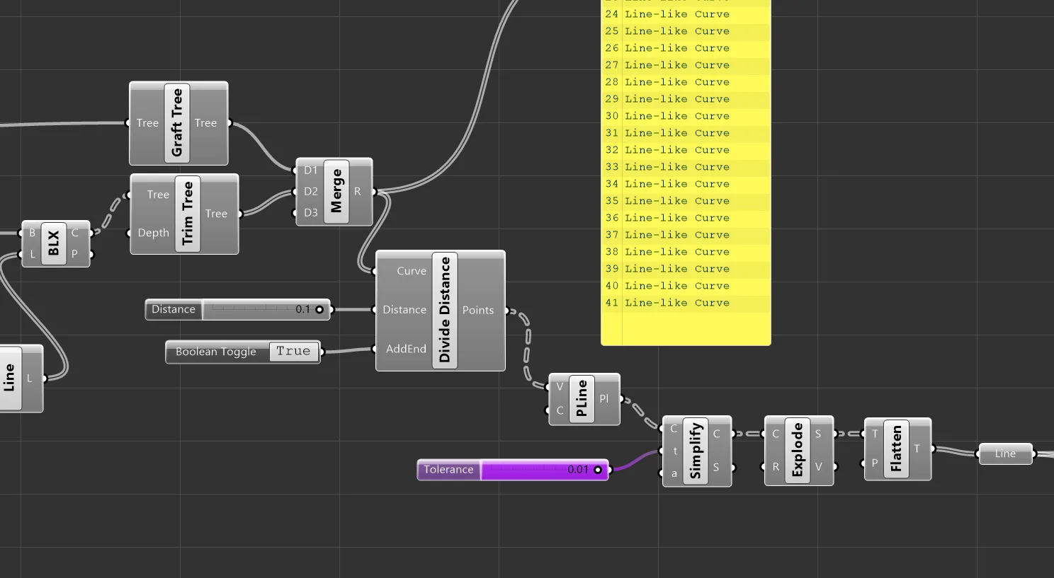
The polyline output is then exploded into individual line segments, ready for conversion into G-code commands.
I verified the slicer on a 1.5mm / 5 layer object:
G Code Converter
I added the should-extrude condition and calculated the extrusion value:
def gcode_move(current_pos, next_pos, feed_rate=None, should_extrude=False):
    # Start with "G1" as command
    move_command_str = COMMAND_MOVE

    # Compare X positions
    if (not are_floats_equal(current_pos[0],next_pos[0])):
        x_value = float_to_string(next_pos[0], precision=XYZ_VALUE_PRECISION)
        move_command_str += " " + PARAM_X + x_value

    # Compare Y positions
    if (not are_floats_equal(current_pos[1], next_pos[1])):
        y_value = float_to_string(next_pos[1], precision=XYZ_VALUE_PRECISION)
        move_command_str += " " + PARAM_Y + y_value

    # Compare Z position
    if (not are_floats_equal(current_pos[2], next_pos[2])):
        z_value = float_to_string(next_pos[2], precision=XYZ_VALUE_PRECISION)
        move_command_str += " " + PARAM_Z + z_value

    pi = 3.14159

    if(should_extrude):
        distance_3d = get_distance_3d(current_pos, next_pos)
        area_out = (layer_height * (extrusion_width - layer_height)) + (pi * (layer_height/2)**2)
        volume_out = area_out * distance_3d
        extrusion_length = volume_out / (pi * (filament_diameter/2)**2)

        e_value = float_to_string(extrusion_length, precision=E_VALUE_PRECISION)
        move_command_str += " " + PARAM_E + e_value

    if (feed_rate is not None):
        feed_rate_value = round(feed_rate)
        move_command_str += " " + PARAM_F + str(feed_rate_value)

    move_command_str = move_command_str.strip(" ")
    return move_command_str
For G-Code generation, I checked if the z position of the next line start position was greater than the current position, and if so, did a z-only correction at the current position to the new z position. The subsequent horizontal travel to reach that line start position is taken care of in the next line_start_position check.
The slicer generator contours from bottom-up so z sorting should always be correct.
Current position is updated as each g code command is generated, such that this alorithm mirrors the nozzle position of the printer.
Start, commands, and end G Code are merged before output.
def generate_gcode():
    current_position = [0, 0, 0]
    all_move_commands = []

    for i in range(0, len(lines)):
        line = lines[i]
        line_start_position = line.From
        line_end_position = line.To

        if(line_start_position[2] > current_position[2]):
            new_z_point = [current_position[0], current_position[1], line_start_position[2]]
            z_move_string = gcode_move(current_position, new_z_point, feed_rate=layer_change_feed_rate, should_extrude=False)
            all_move_commands.append(z_move_string)
            current_position = new_z_point

        if not is_same_pt(current_position, line_start_position):
            move_to_line_start_command = gcode_move(current_position, line_start_position, feed_rate=travel_feed_rate)
            all_move_commands.append(move_to_line_start_command)
            current_position = line_start_position

        if is_same_pt(current_position, line_start_position):
            extrusion_command_string = gcode_move(current_position, line_end_position, feed_rate=extrusion_feed_rate, should_extrude=True)
            all_move_commands.append(extrusion_command_string)
            current_position = line_end_position

    gcode_lines = start_gcode_lines + all_move_commands + end_gcode_lines
    output = COMMAND_DELIMITER.join(gcode_lines)

    return output
Validation
Zupfe confirmed appearance and the simulation worked in the intended order:
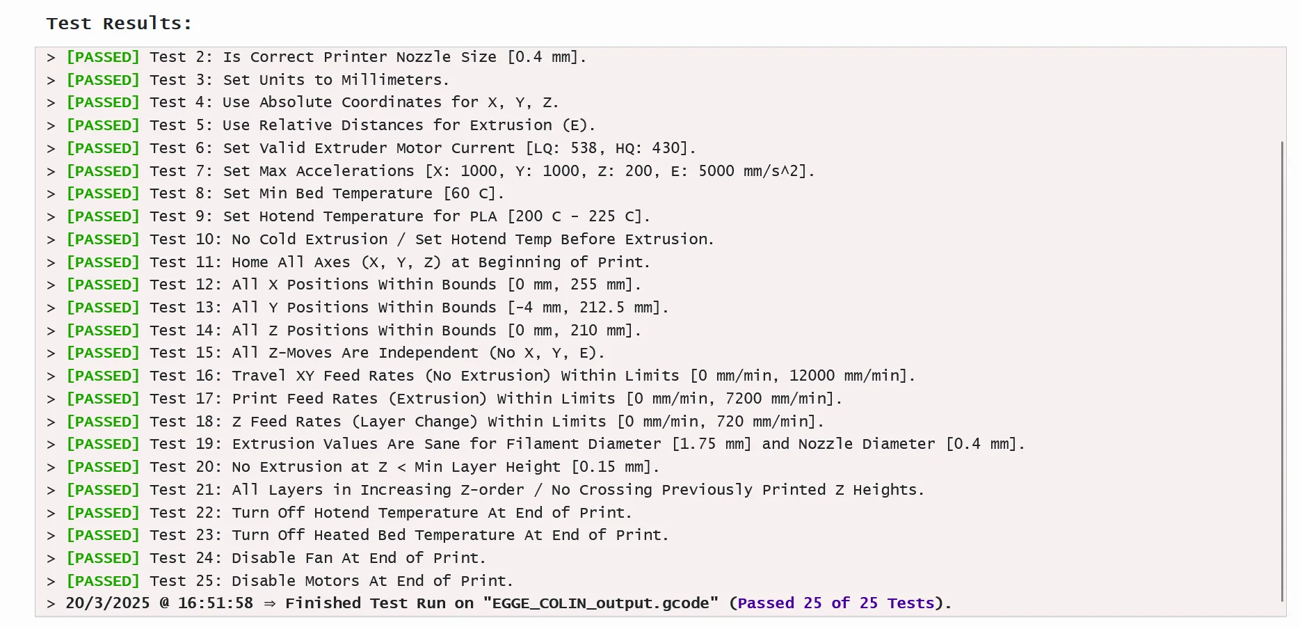
G-Code passed all tests!
Files
https://drive.google.com/drive/folders/19kgNmLkUKKiFjsrI1IN37ESHJQDgPjEs?usp=sharing
Testing and Fabrication
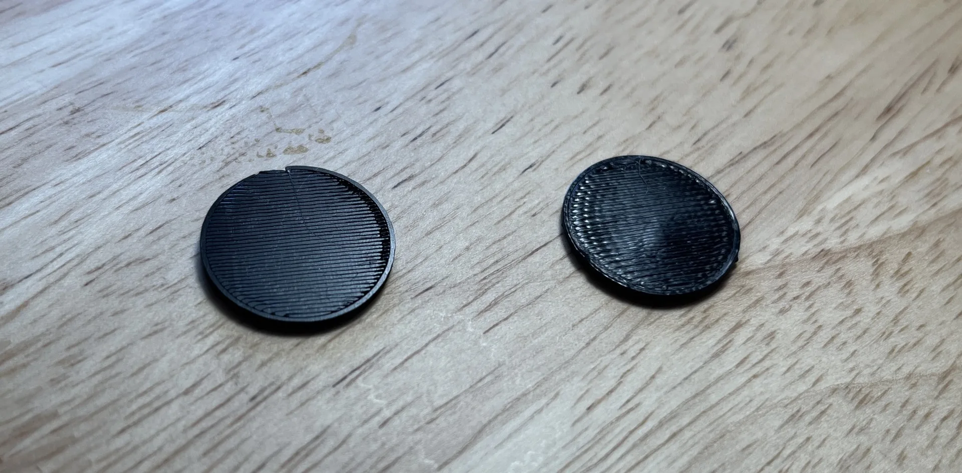
I printed the test cylinder sliced with Prusa slicer (right) and then the output G-Code (left).
The generated G code infil was a little cleaner - the non-optimized lines making a crisper, flatter surface than the optimized/snaking lines of the prusa sliced print. This also may have been due to the printer being warmed up after the the first print.