Overview
This project implements biomimetic growth to create organic shapes that interact and collide with pre-existing rigid forms. The goal was to create or “grow” structures that naturally wrap around or support other objects without post-processing or boolean operations. The primary form is shaped entirely by virtual forces and physical constraints, including collisions with rigidbodies, attractor forces, and gravity. Then, a secondary detailing pass is applied to some objects to create different surface textures.
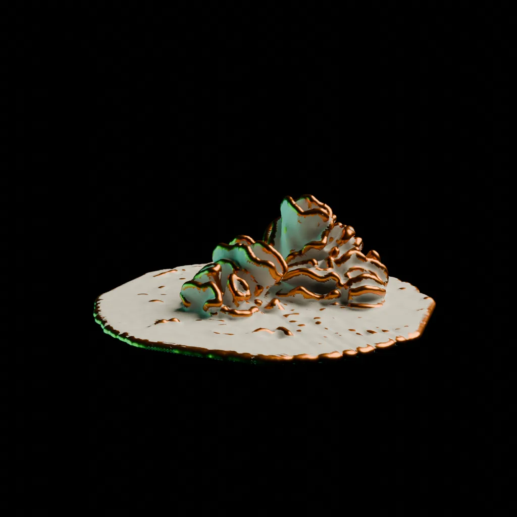
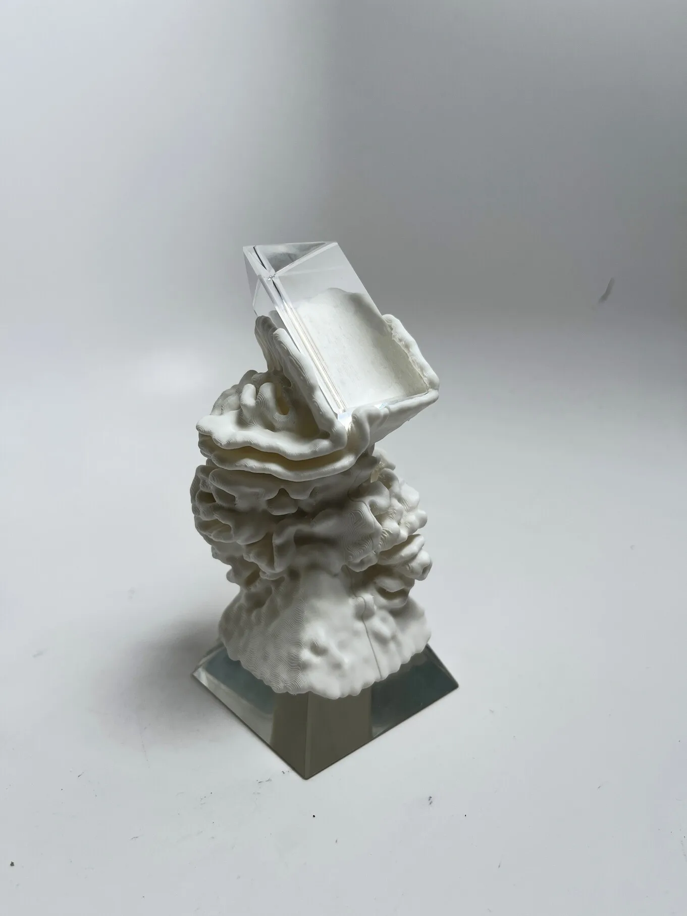
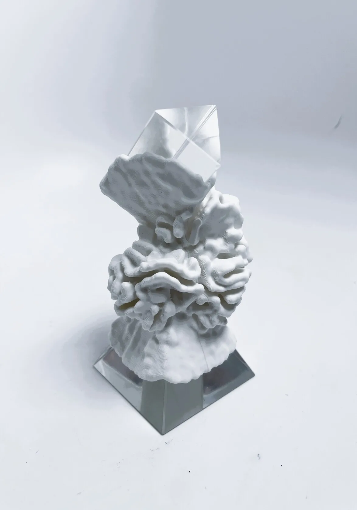
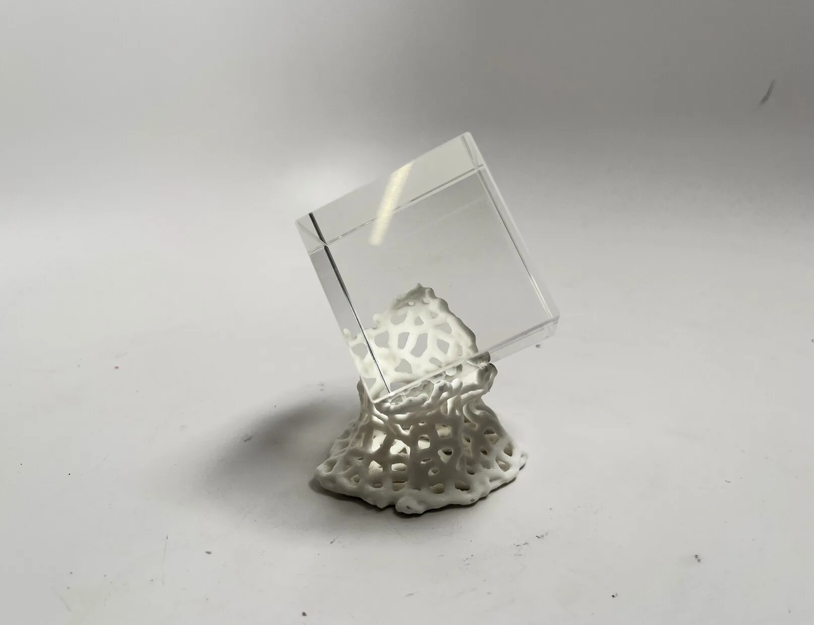
The output is small 3D printed sculptures that appear to have grown around glass primitive geometries.
The project formed initially as an intent to explore fabricating a “frozen” simulation of some kind. The aesthetic was inspired by algorithmic ceramics works by Brian Knep (https://www.blep.com/works/embryos/) as well as architectural concepts by Michael Hansmeyer (https://www.michael-hansmeyer.com/phenomena) - both of which led me towards a differential growth simulation.
Implementation
The simulation is built in Blender Geometry Nodes, and runs iteratively on the vertices in a mesh. The primary growth algorithm is Differential Growth.
Differential Growth
Differential growth runs on points in a curve, and is driven by a few factors:
Growth Force: Points are pushed apart in order to expand - this can be from normal direction, curvature, or arbitary forces.
Spacing Constraint: New points are inserted where the distance between neighbors exceeds a threshold, maintaining even distribution.
Repulsion: Points repel each other to avoid overlap, (or in this case, self-collide) creating branching or spreading patterns.
Constraints: External forces or collision detection can guide growth around obstacles or toward targets.
Geometry Nodes Implementation
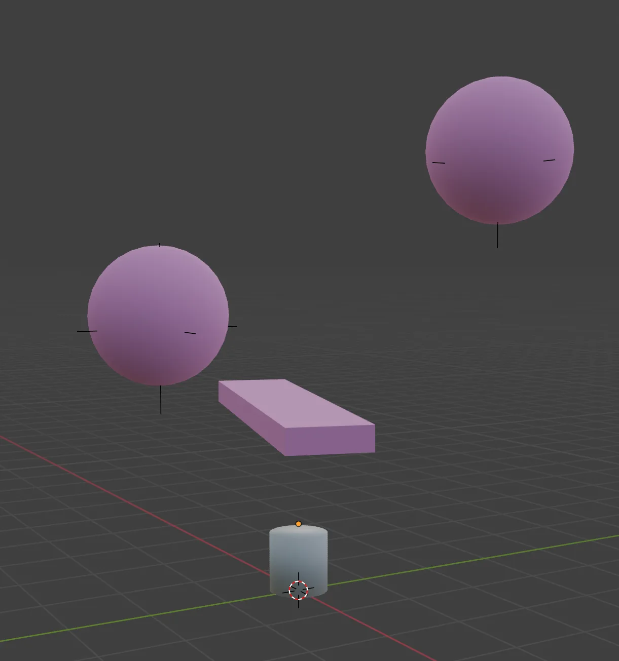
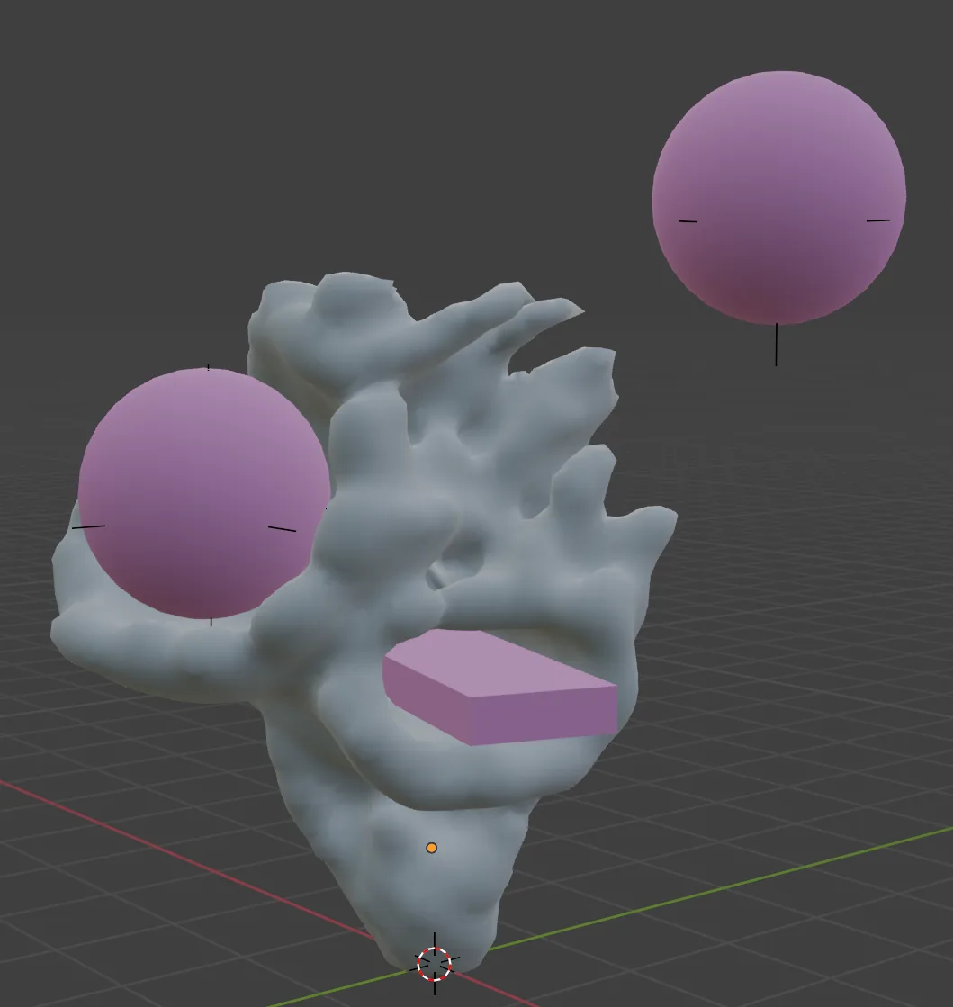
First the user places start geometry (in this case, a cylinder), and collision geometry in the scene. A geometry nodes graph is added to the primary geometry. The collision geometry should be joined into a single mesh.
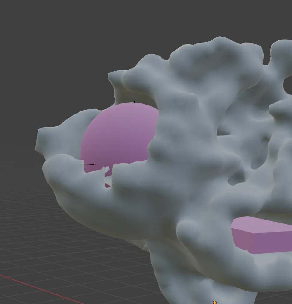
In the above simulation above, there are two attractor points within the spheres.
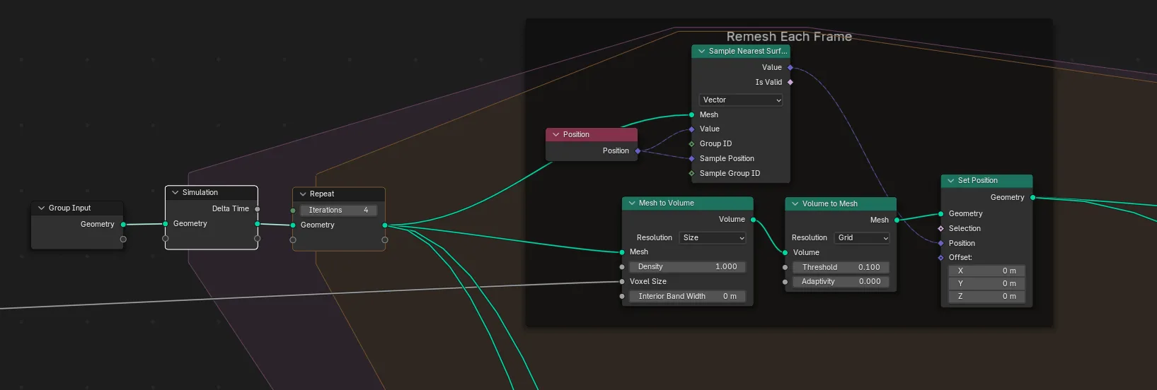
A simulation is run on the vertices of any input geometry. Each frame, the entire geometry is remeshed into a volume of voxels, and then converted back into a mesh. As the vertices expand, the consistent voxel size means new points will be inserted dynamically, maintaining consistent regional mesh resolution.
Forces
Normals: The the vertices move in their normal direction. The speed of this growth is scaled based on the remaining forces.
Gravity Threshold: This limits growth the vertices with normals aiming upward past a certain threshold
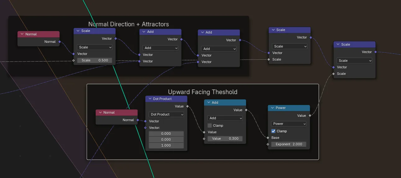
Curvature: How sharp an angle the normals have relative to nearby vertices - this causes faster growth along ridges
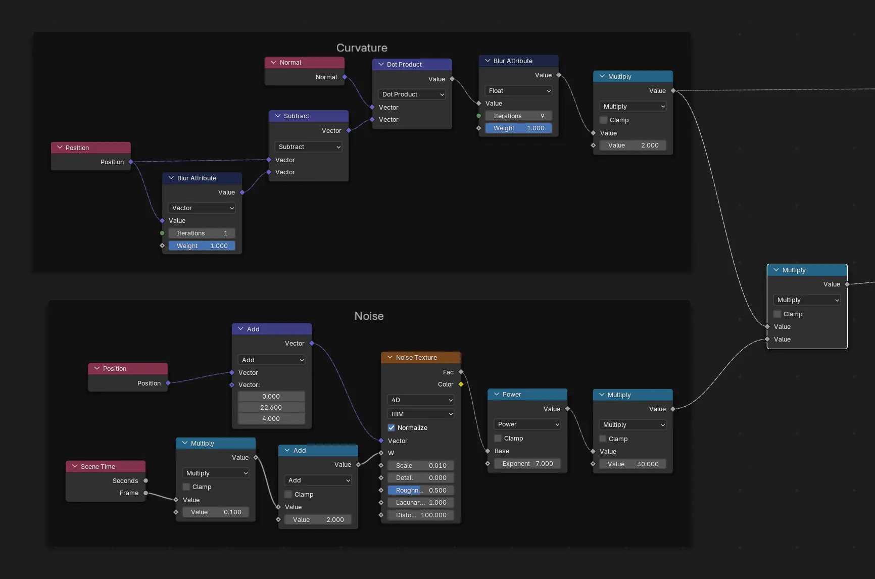
Noise: 4D perlin noise is applied to the growth rate in order to spur new growths and create variations
Attractor forces: The growth is stronger in the direction of attractor points (two possible attractors in this graph)
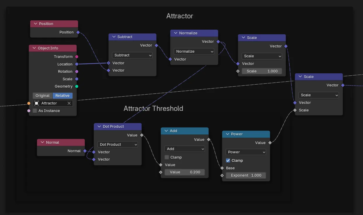
Attractor vectors are calculated by subtracting the vertex position from the attractor position. In order to prevent attractors from cancelling each other, attraction force is masked by normal direction - only vertices facing the attractor will grow towards it.
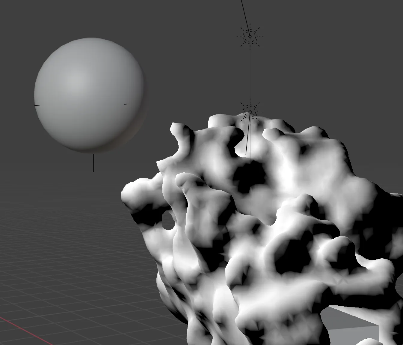
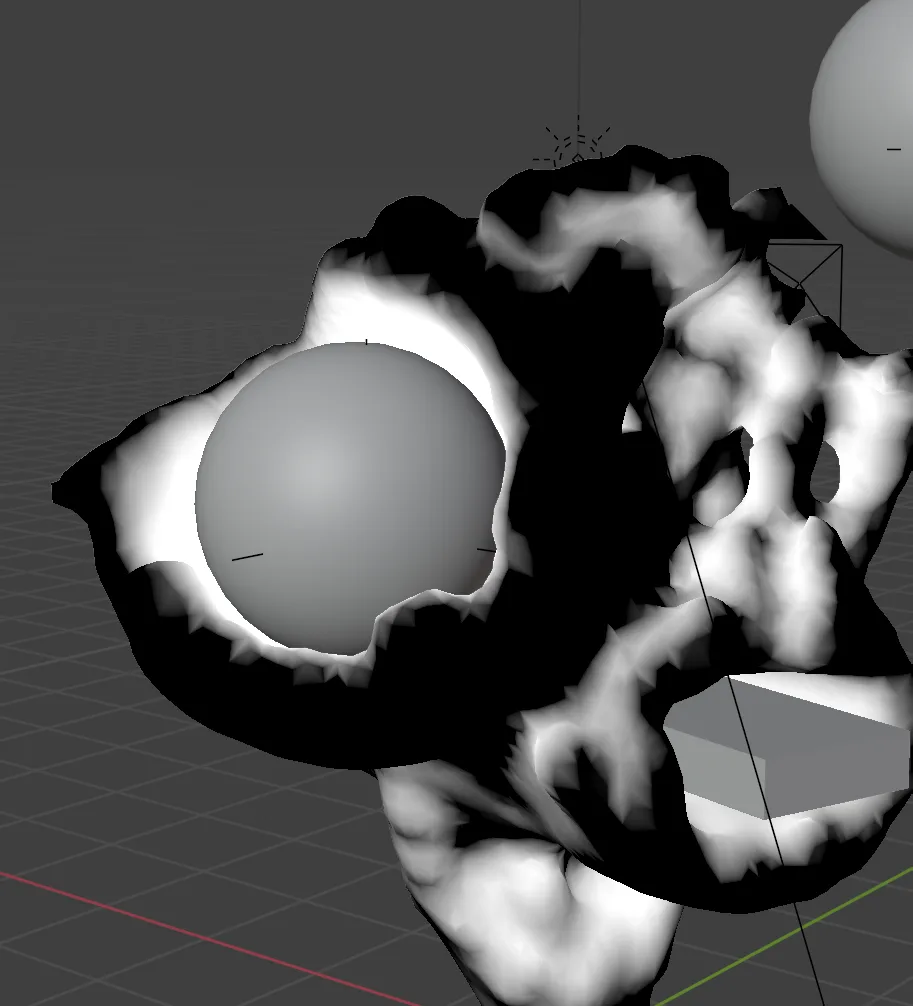
Here, the attraction forces are visualized in white. You can think of an attractor as a light source, and vertices facing the light source will grow faster.
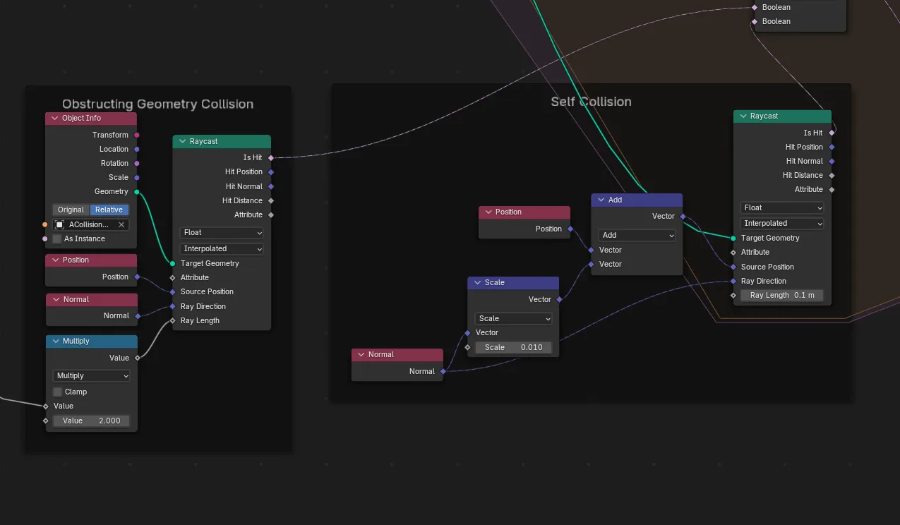
Collision
Collision checks are done with a raycast. A ray is fired from each vertex in its normal direction. If it detects an obstructing object (or self collides) it will stop growing in that direction.
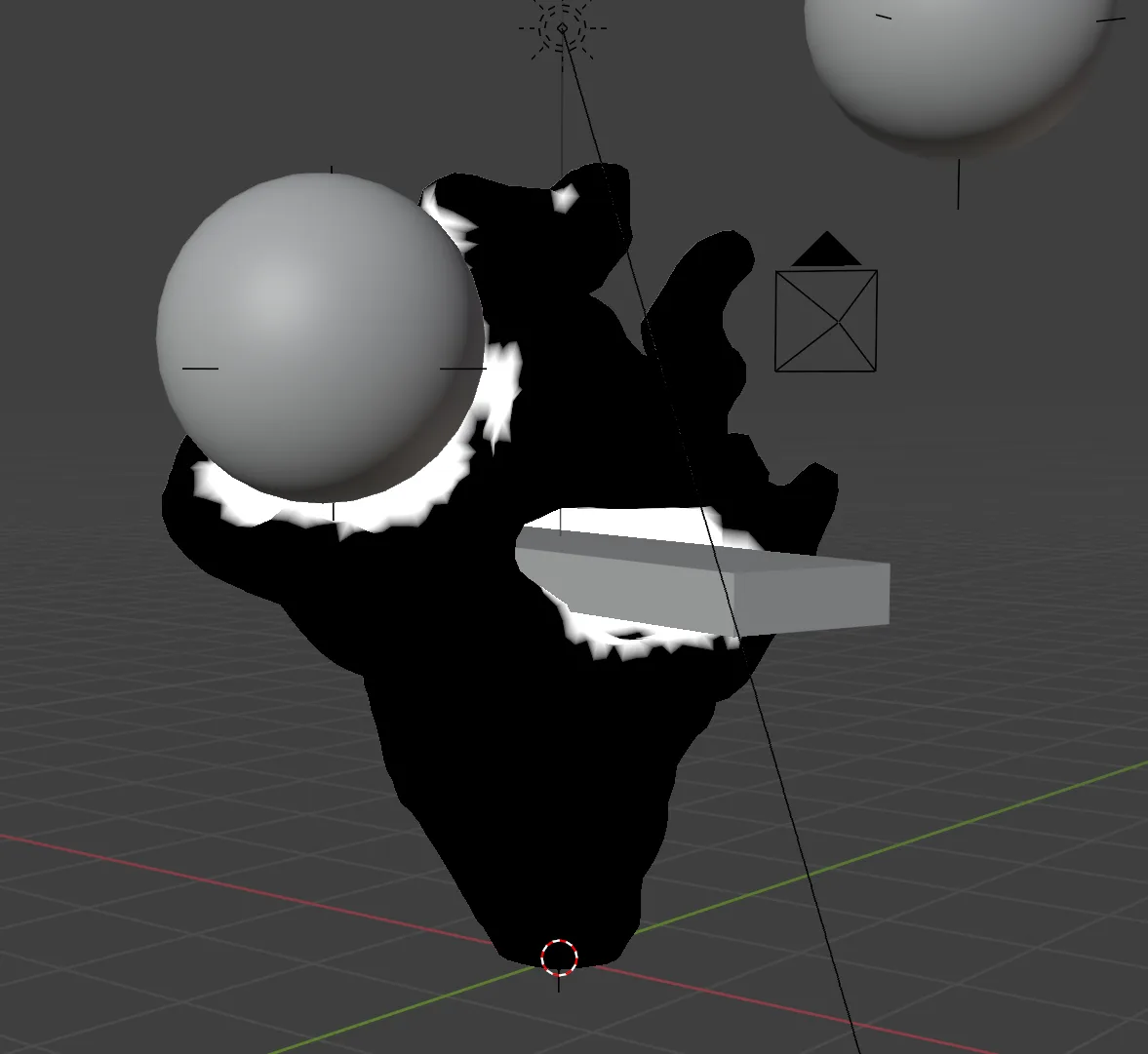
Above, all colliding vertices are highlighted in white.
To grow around objects, we find vertices adjacent to colliding vertices. A growth vector is added in this direction, so the growth is accelerated along the tangent of the collision.
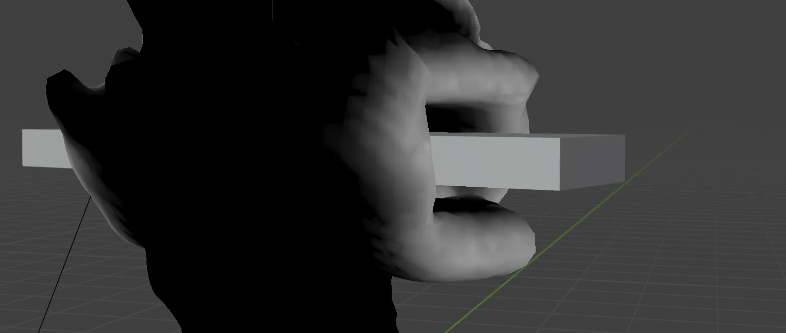
Tangental growth vectors in white
If an attractor is placed inside of a collision object, the tangential growth will cause the form to rapidly grow around and consume that object:
Parameters
Every aspect of the simulation is parameterized.
Voxel size determines mesh resolution when remeshing, but also dictates the “viscosity” of the substance since the curvature and collision resolution is more precise with smaller voxels.
Normal Multiplier Sets baseline growth speed, influenced by other forces
Curvature Multiplier Influence of curvatures
Noise Scale Scale of noise pattern (smaller value is “larger” noise pattern)
Noise Power An exponent value which changes the sharpness of noise
Noise Multiplier Influence of noise
Noise / Curve Combine Is curvature added to or multiplied by noise
Attractor Multipliers Influence of attraction points
Tangental Growth Scale Scale of growth tangential to collision
Fixed Variables: (these remained the same between outputs)
Collision distance dictates radius around collision objects, whereas self collision distance can influence the texture of the shape as it can create or soften grooves and creases.
Growth Animation
Here is an animated demonstration of the algorithm. The material highlights the curvature (the biggest influence in this case) with a metalic patina. Note the curves “reaching” towards attractors, as well as faster growth along colliding surfaces:
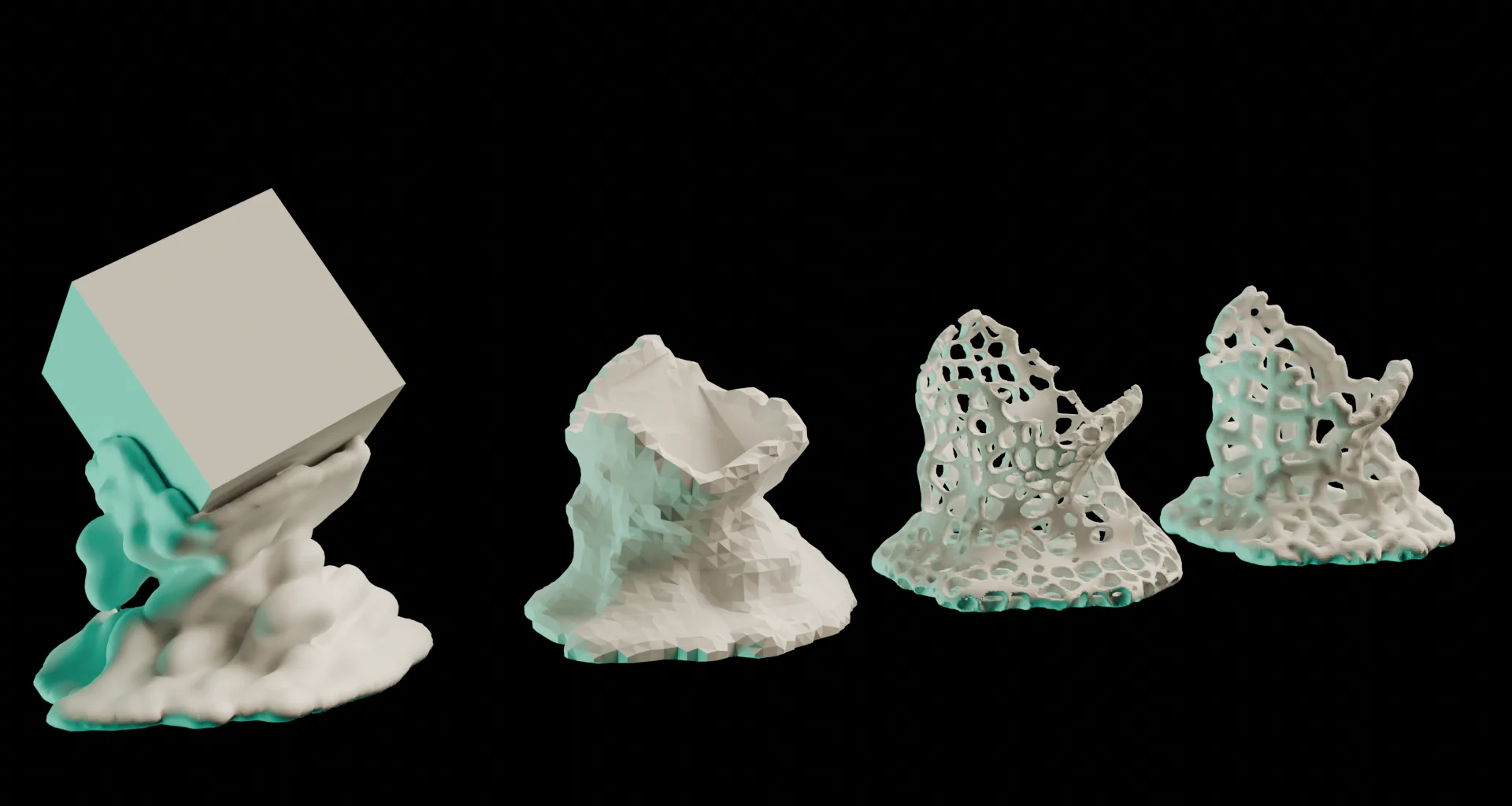
Primary Outputs
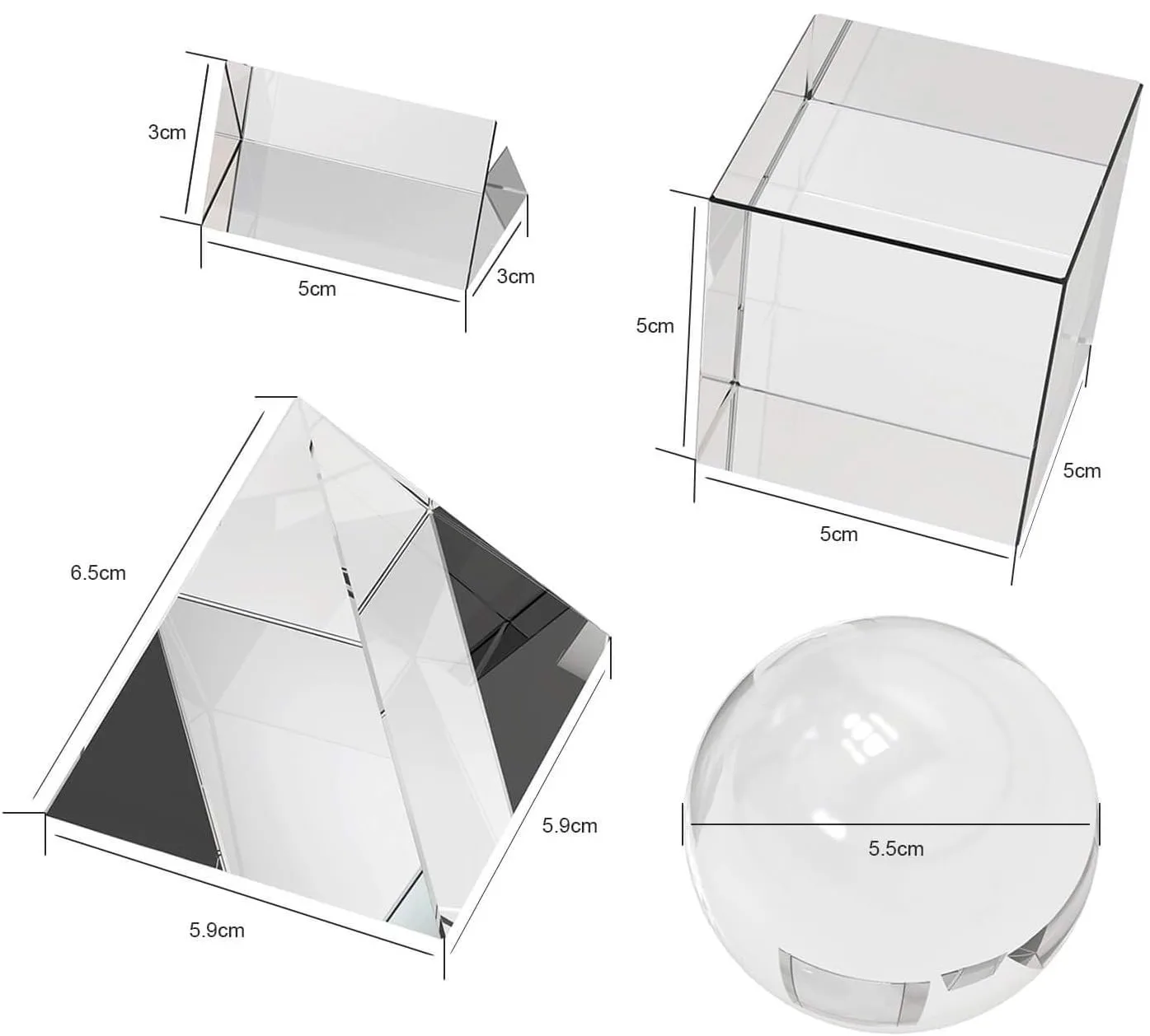
To create the final sculptures, the simulation was run to scale with a collection of glass primitives serving as the basis for the virtual collision geometry:
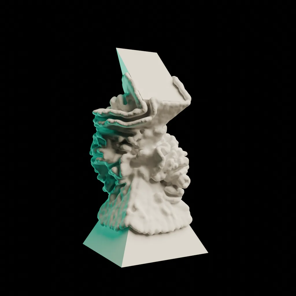
Dual Prisms
| Parameter | Value |
|---|---|
| Iterations | 55 |
| Voxel Size | 0.075 |
| Normal Scale | 1.0 |
| Curvature Multiplier | 2 |
| Noise Scale | 0.01 |
| Noise Power | 6 |
| Noise Multiplier | 25 |
| Attractor 1 Scale | 1.0 |
| Attractor 2 Scale | 2.0 |
| Tangental Growth Scale | 0.3 |
| Gravity Threshold | Yes |
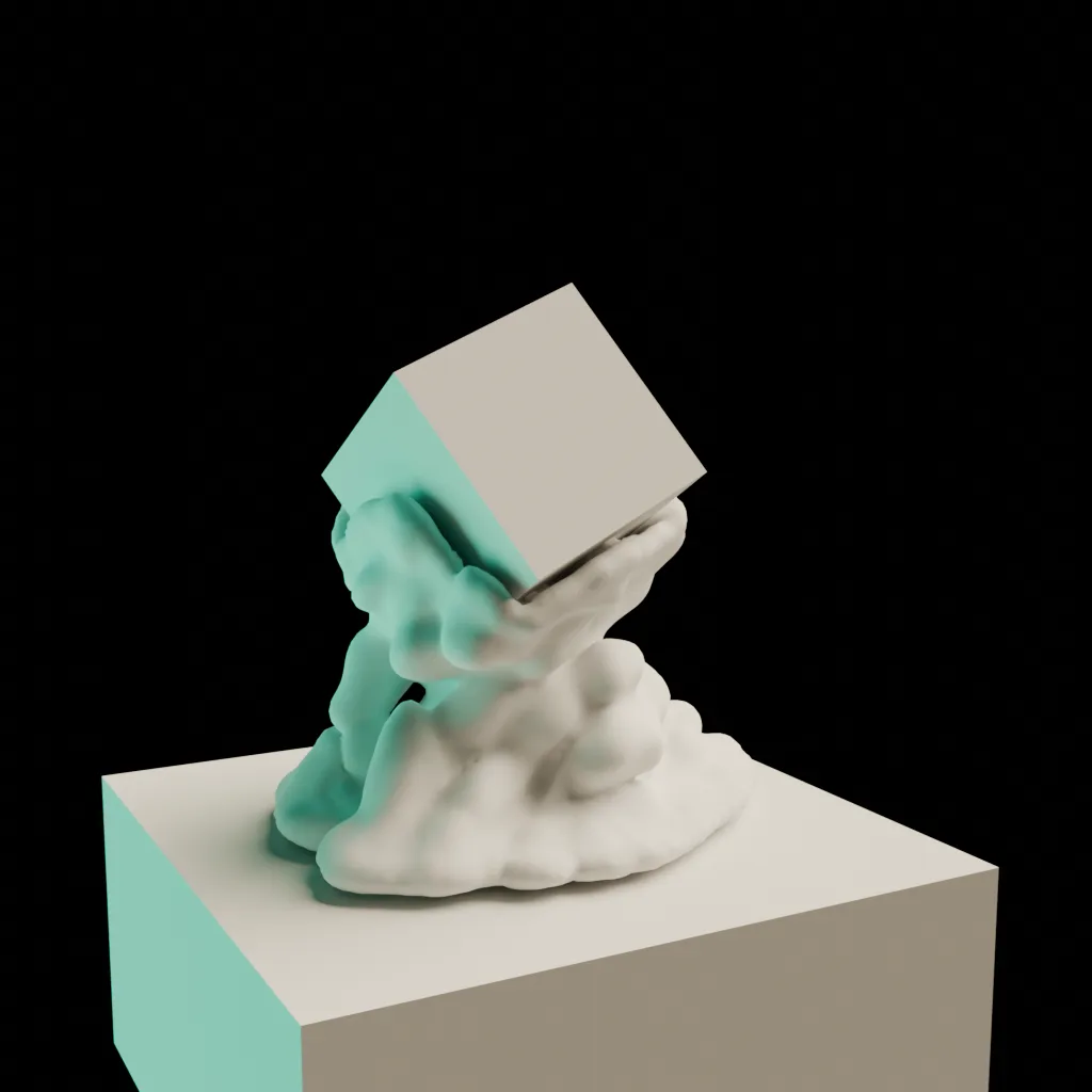
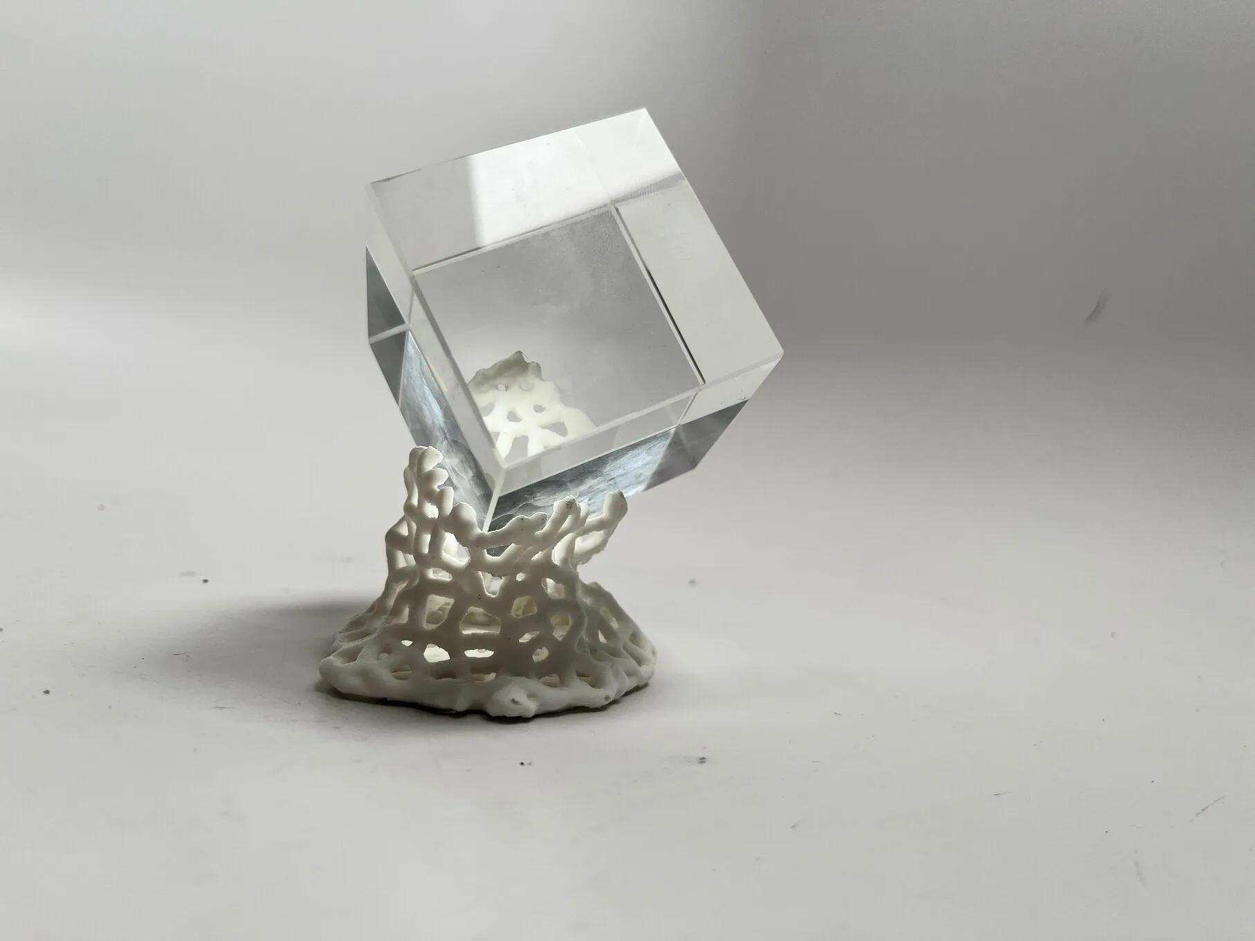
Cube
| Parameter | Value |
|---|---|
| Iterations | 58 |
| Voxel Size | 0.150 |
| Normal Scale | 1.0 |
| Curvature Multiplier | 0.5 |
| Noise Scale | 0.005 |
| Noise Power | 4 |
| Noise Multiplier | 0.250 |
| Attractor 1 Scale | 2.0 |
| Attractor 2 Scale | 0.0 |
| Tangental Growth Scale | 0.3 |
| Gravity Threshold | No |
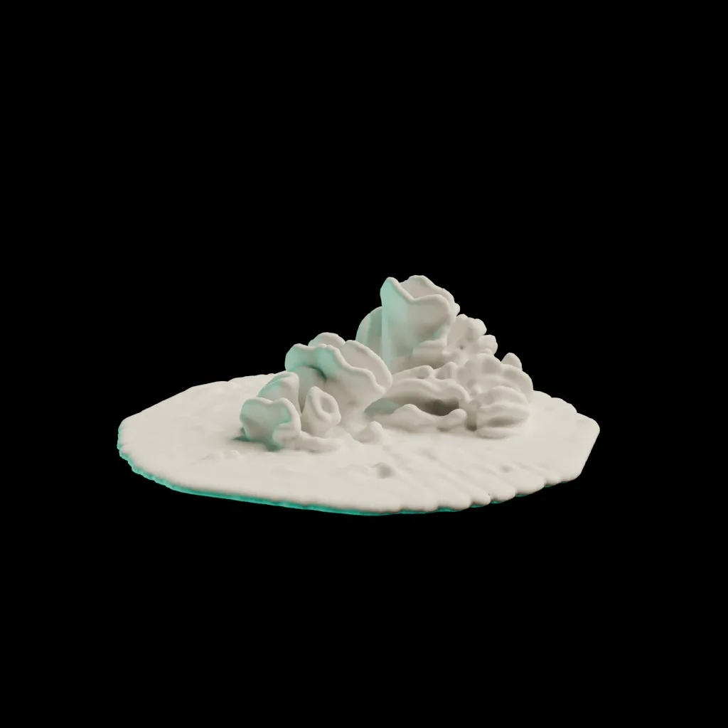
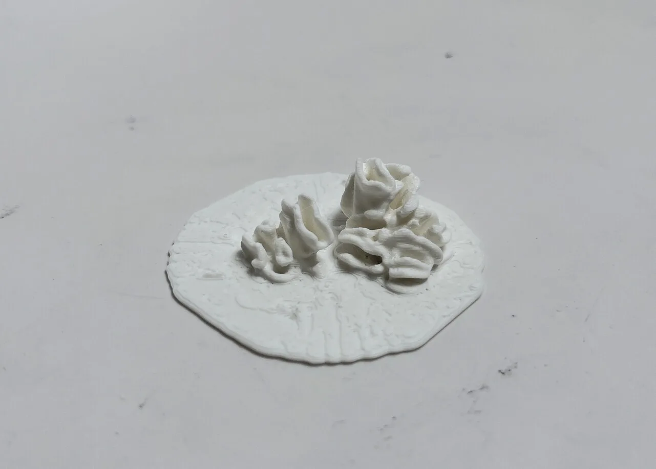
Coral
| Parameter | Value |
|---|---|
| Iterations | 55 |
| Voxel Size | 0.075 |
| Normal Scale | 0.5 |
| Curvature Multiplier | 2.0 |
| Noise Scale | 0.01 |
| Noise Power | 7 |
| Noise Multiplier | 30 |
| Attractor 1 Scale | 0.0 |
| Attractor 2 Scale | 0.0 |
| Tangental Growth Scale | 0.2 |
| Gravity Threshold | Yes |
Post Processing
The natural coral or fungus-like curvatures that resulted from the simulation was visually interesting enough to serve as the surface for the objects. However, a secondary pass was an option for making simpler or lower fidelity objects more appealing, or for creating a different printing structure.
For the “Cube” output, I applied a voronoi texture to the shell before printing. This was done in Blender with an additional geometry nodes graph.
First the object is remeshed at a higher resolution to create sufficient geometry. Then, vertex positions are compared with a 3D voronoi texture - vertices with a texture value greater than a small percentage are deleted, leaving the voronoi shell. At this point the object is a polygonal shell without depth, and would not be printable, so the faces are extruded.
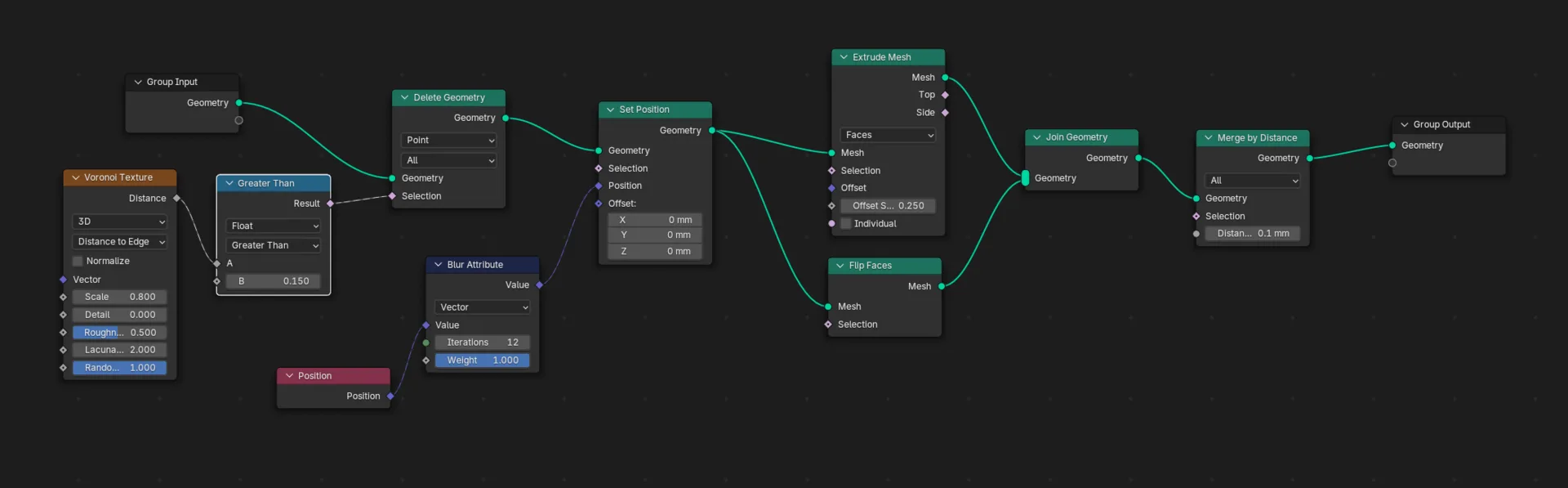 Geometry Nodes graph for voronoi post process
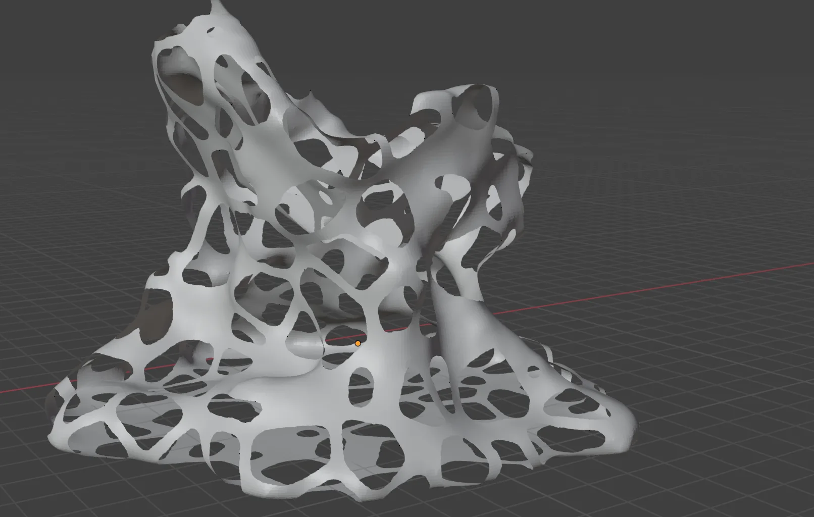
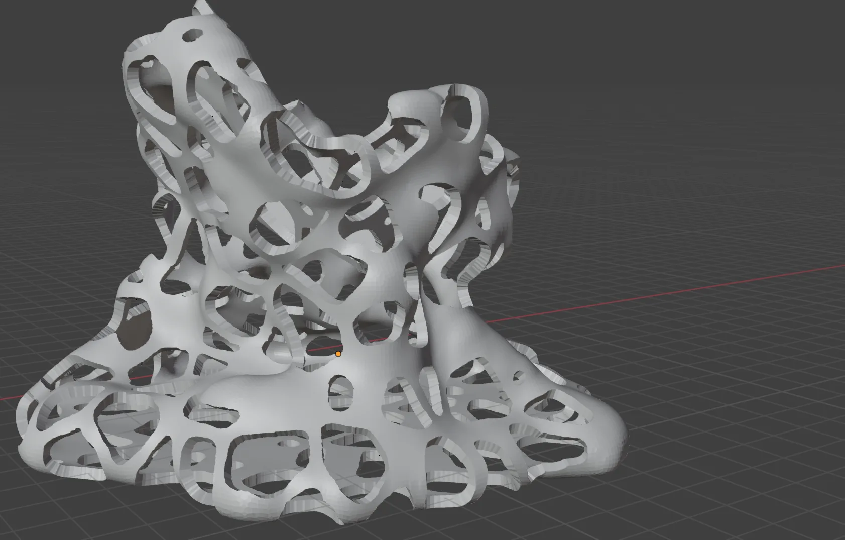
Hull and extrusion
Several failed printing attempts led to further arbitrary processing - including additional voxel remeshing as well as scaling faces by normal direction in order to ensure structure was sound and printable.
Fabrication
The sculptures were 3D printed in matte white PLA, and fitted around their glass primitives.
Prisms
Voronoi
Coral
Print Process Notes
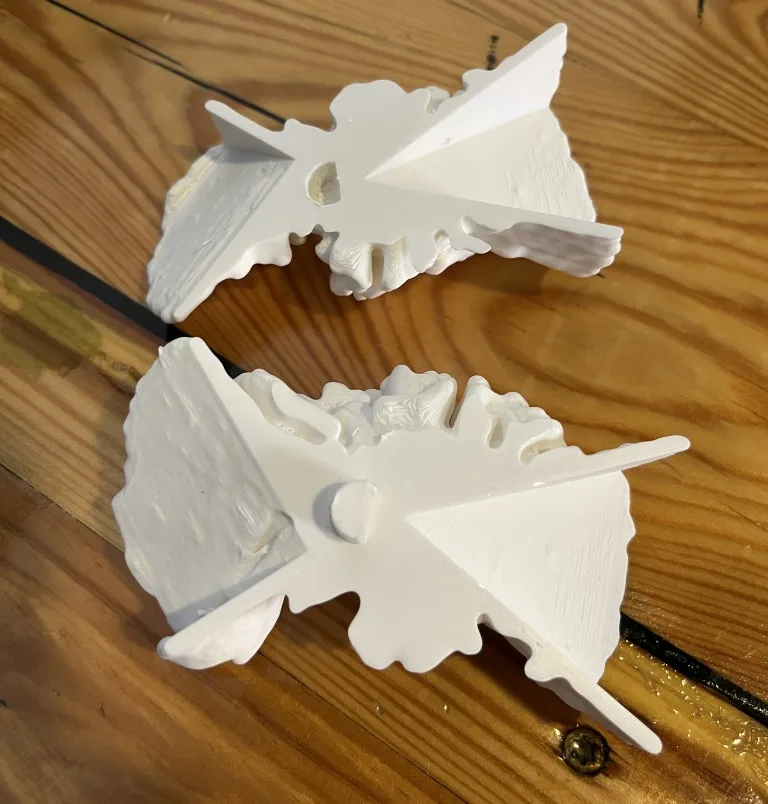
In addition to the iterations on the voronoi above, only one other change needed to be made - the “Dual Prisms” print was split and printed in two parts, with a boolean joint connecting them:
Closing Thoughts
The resulting shapes are very satisfying, with complex outputs coming from a simulation that is fairly simple when broken down to a single iteration.
The fabrication process went reasonably smoothly. Tuning print parameters to handle the detailed coral-like structures was a challenge. Ultimately these printed cleanly (although required an hour or so of removing support fills with tweezers).
The differential growth algorithm has a few opportunities for expansion I would like to explore:
- Multiple growing bodies that collide and repel each other
- Animating parameters over time
- Collision events - eg change parameters based on collisions with certain objects (eg. have one object encourage growth and another repel)
Most of these features are possible in the current implementation with small changes.
I would also like to explore implementing a similar system in Grasshopper so that it is compatible with the rest of its parametric CAD toolset.